


Take the first step in raising your robot army and meet the Arduino, the microcontroller designed to be approachable and fun. From blinky lights to motors, temperature sensors to wi-fi, RFID to MIDI, you can make your code do stuff.
Learn to look at projects in terms of outputs and inputs as this article walks you through the code and electronics to blink an LED and react to a pushbutton. You'll also see how simple it is to control a servo motor.
Your experience as a developer will apply directly to the Arduino, which uses a language that extends C++. You'll also need to learn about electronics, and the Arduino makes a great platform for doing so. I'll introduce the basics here, to start your journey.
Use https://www.arduino.cc/ to see descriptions of the different Arduino models, find places to buy one, and refer to the language reference.
Your First Output: Blink an LED
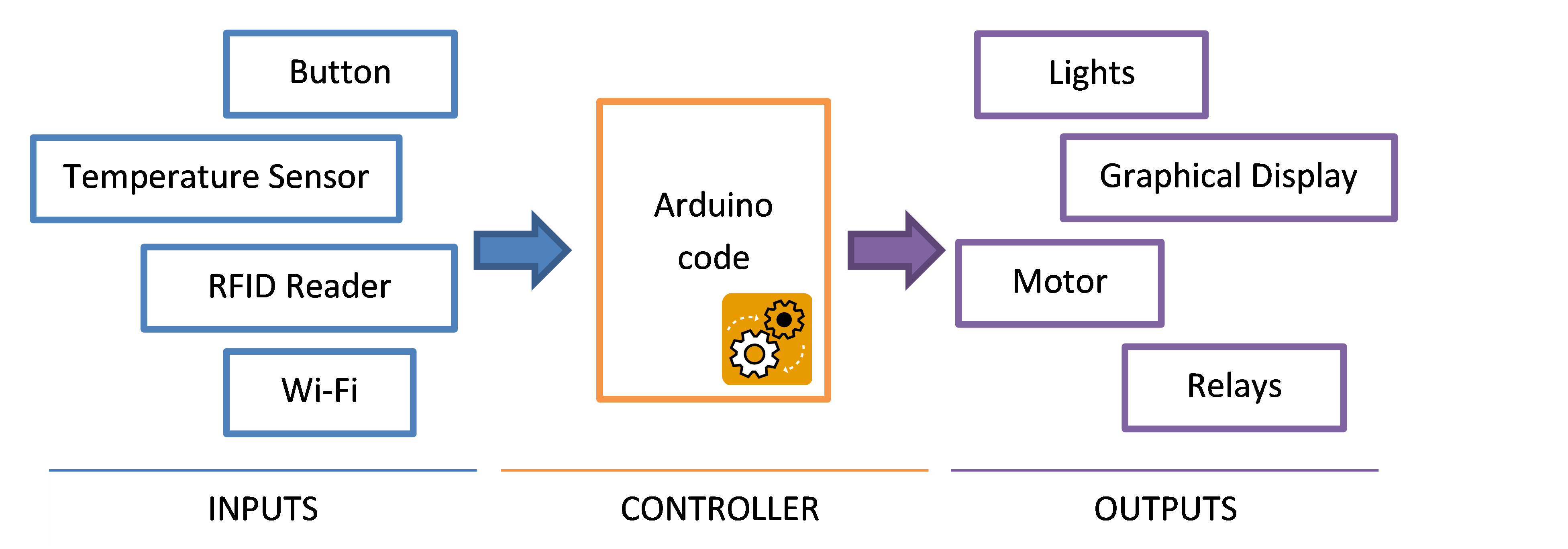
Making an LED (light-emitting diode) blink is the “hello, world” of electronics. You can think of your Arduino projects as inputs (buttons and sensors that feed facts about the world into your code), outputs (lights, buzzers, and motors that manifest your code's intent), and your code running on the Arduino microcontroller as the conductor between them. See Figure 1 for an illustration. With that perspective, let's start by controlling your first output.
Components You'll Need
- Arduino
- USB cable
- Computer running the Arduino IDE
- LED
Connect the LED
You connect components to your Arduino via the pin headers running down both sides of it. Small text printed on the green circuit board labels the pins; use that to find the pin headers for pin 13 and the GND (ground) pin. See Figure 2.
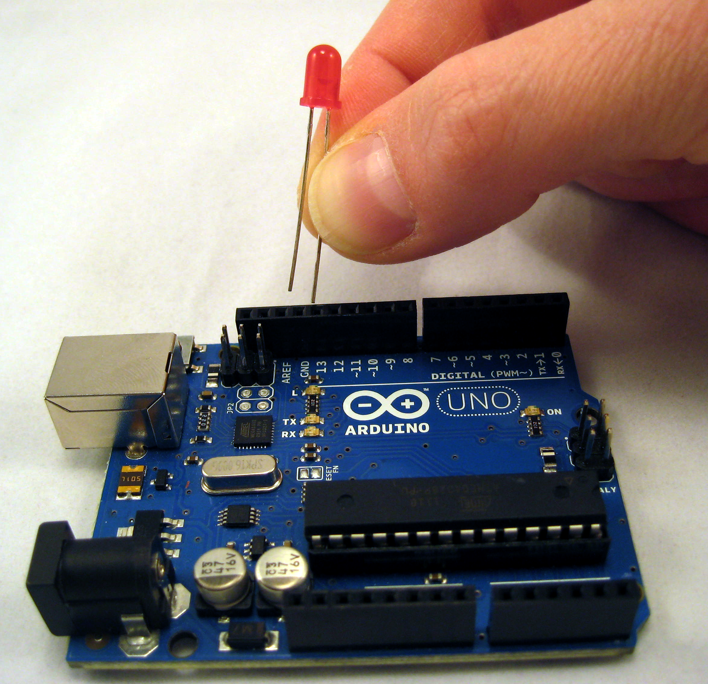
An LED has two wires, called leads, and by convention they are different lengths. Plug the shorter lead (called the cathode) into the GND pin header and the longer lead (the anode) into the 13 pin header. If you get it backwards, the LED simply won't light, but it's otherwise harmless. If your LED is not lighting up when you get to the final step of testing your project, try flipping it around.
Write the Code
Arduino programs are called sketches. Every sketch must contain a setup() function and a loop() function. For reuse and readability, you can extract your logic into additional functions, but you have to have at least those two.
The setup() function runs once, when your sketch starts, and the loop() function runs continuously, like the event loop in a game.
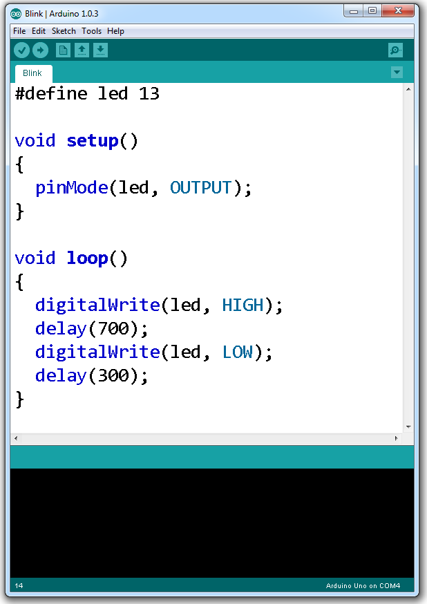
This sketch blinks the LED in a syncopated rhythm. Enter the code into the Arduino IDE, shown in Figure 3. I'll discuss the sketch line by line.
#define led 13

void setup() {
  pinMode(led, OUTPUT);
}

void loop() {
  digitalWrite(led, HIGH);
  delay(700);
  digitalWrite(led, LOW);
  delay(300);
}
The first line in our blinky LED sketch is a precompiler directive to define the text “led” as a stand-in for “13”, to make the code easier to read by giving the pin a meaningful name, and easier to change if you decide to use a different pin.
The setup() function calls the Arduino's pinMode() function to establish pin 13 as an output pin, meaning the sketch writes instructions out to that pin. Later, when you add a pushbutton to the project, you'll set up the button's pin as an input, a pin from which you'll read information. For an explanation of what the Arduino does electrically when you call pinMode(), see https://arduino.cc/en/Tutorial/DigitalPins.
Inside the loop() function, the sketch turns the LED on, pauses the thread, turns the LED off, and pauses again. The Arduino calls this function repeatedly, for as long as it has power. The digitalWrite() function takes two arguments: the pin to control, and the signal to send. As you might imagine, the Arduino also supports a digitalRead() function, which you'll use later when you read the state of a button, and analogWrite() and analogRead() functions, for values that are from a range instead of binary.
Lastly, the delay() function causes the program's execution to wait for the specified number of milliseconds. Without the delay, you wouldn't see the LED blink, because it would switch on and off faster than you could perceive.
Upload the Sketch
I used to think getting code onto a microcontroller was too daunting to attempt - something those hardware people do. The Arduino makes this delightfully simple.
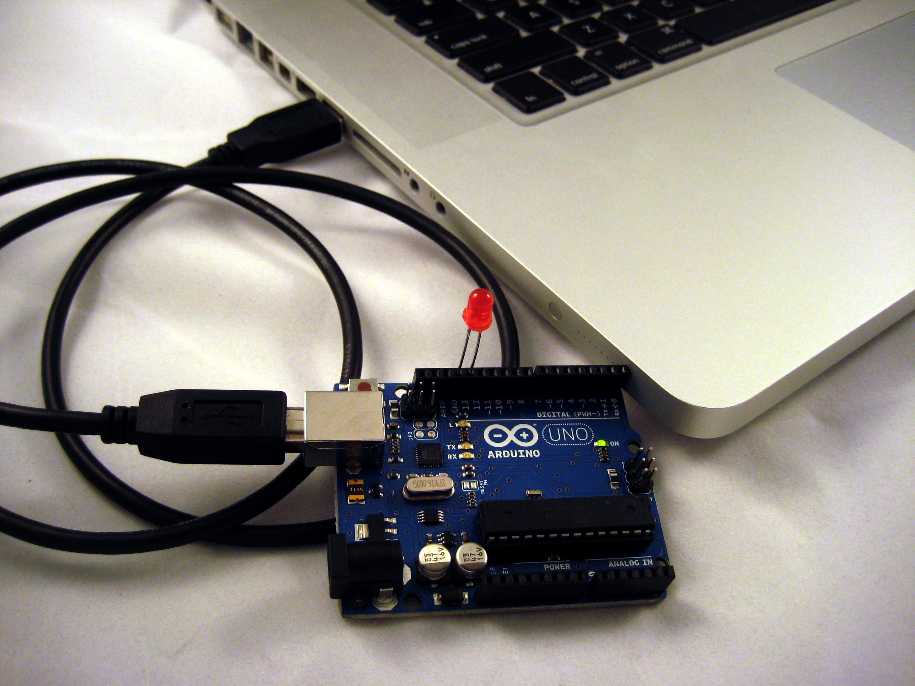
Use a USB cable to connect the Arduino to your computer, as in Figure 4, and click the Upload button in the Arduino IDE. The Getting Started guide at https://arduino.cc/en/Guide/HomePage provides operating system-specific instructions for selecting the right port and uploading your sketch.
The chip on an Arduino comes preinstalled with a bootloader program. When the board gets power (such as via your computer's USB port), the bootloader listens for new instructions coming over the wire. If it receives a new sketch, it stores that and starts it; if not, it runs the last sketch it stored.
Expected Results
Here are the steps you just completed.
- You plugged an electronics component into the pin headers on your Arduino board; in this case, an LED serves as the output for your sketch.
- You wrote a sketch in the Arduino IDE to tell the microcontroller how to control the LED.
- You uploaded the sketch to your Arduino via USB, and that USB cable is now supplying power to the Arduino.
You should see the LED blinking, on for 700 milliseconds then off for 300 milliseconds. Experiment with making additional calls to digitalWrite() and changing the delay() durations.
Now that your sketch is stored on the Arduino, you could unplug the USB cable and power the board via a 9-volt battery instead.
Listen for an Input: React to a Pushbutton
If you're going to make a tractable robot army, you need to make it respond to your commands. The Arduino can listen for inputs you control, such as buttons, joysticks, and flex sensors, as well as environmental sensors like light, temperature, and humidity sensors.
Let's add a button to the project to turn the LED on and off manually.
Components You'll Need
- Pushbutton
- 10K O resistor
- Breadboard
- Jumper wires for making connections on the breadboard
- The setup from the LED project above
Connect the Button
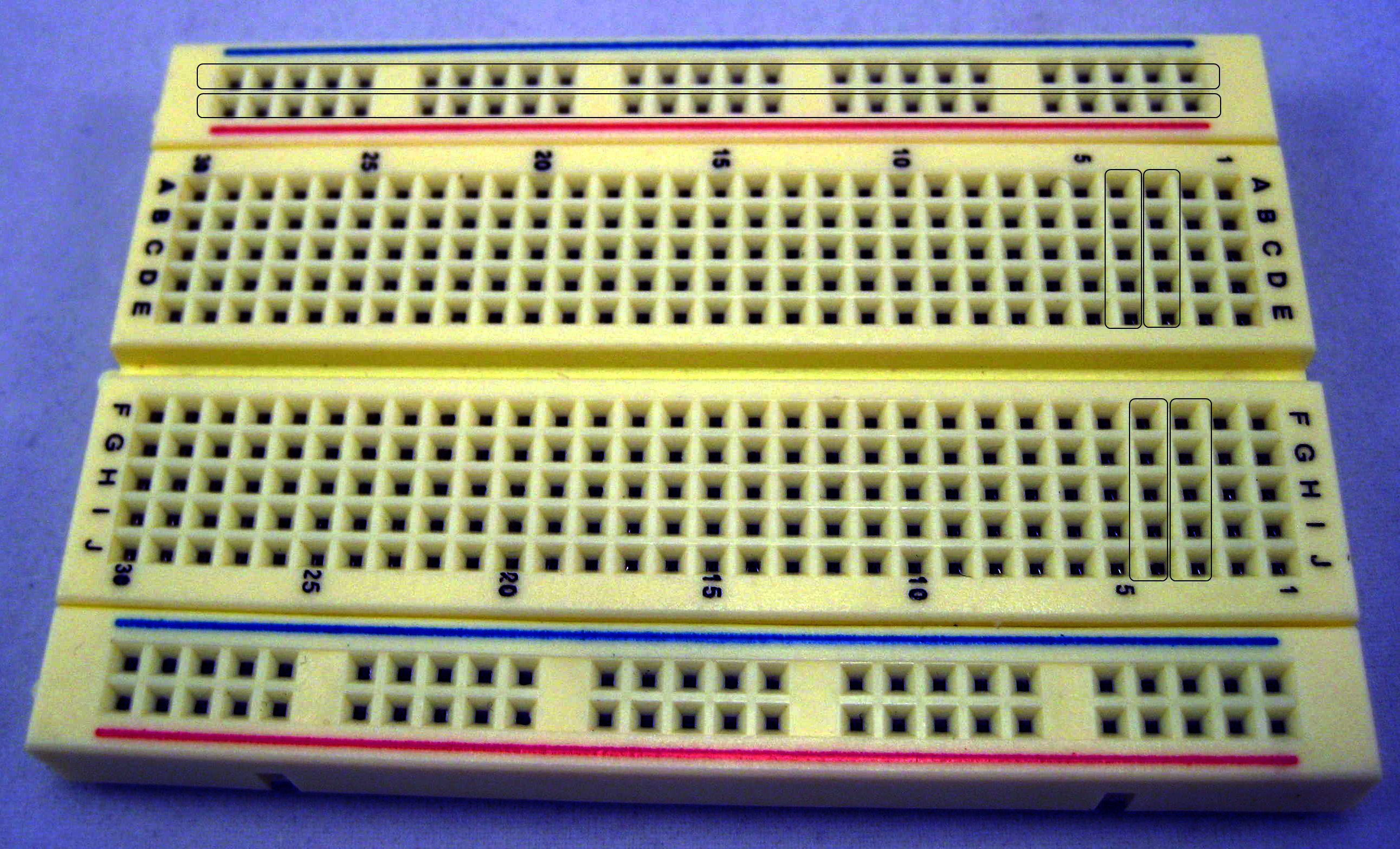
You were able to plug the LED directly into the Arduino because the pins You needed, GND and 13, are side by side. For the button, You need more room to work, so you'll use an electronics breadboard to make connections between the components. See Figure 5 and the sidebar “Breadboards for Prototyping.”
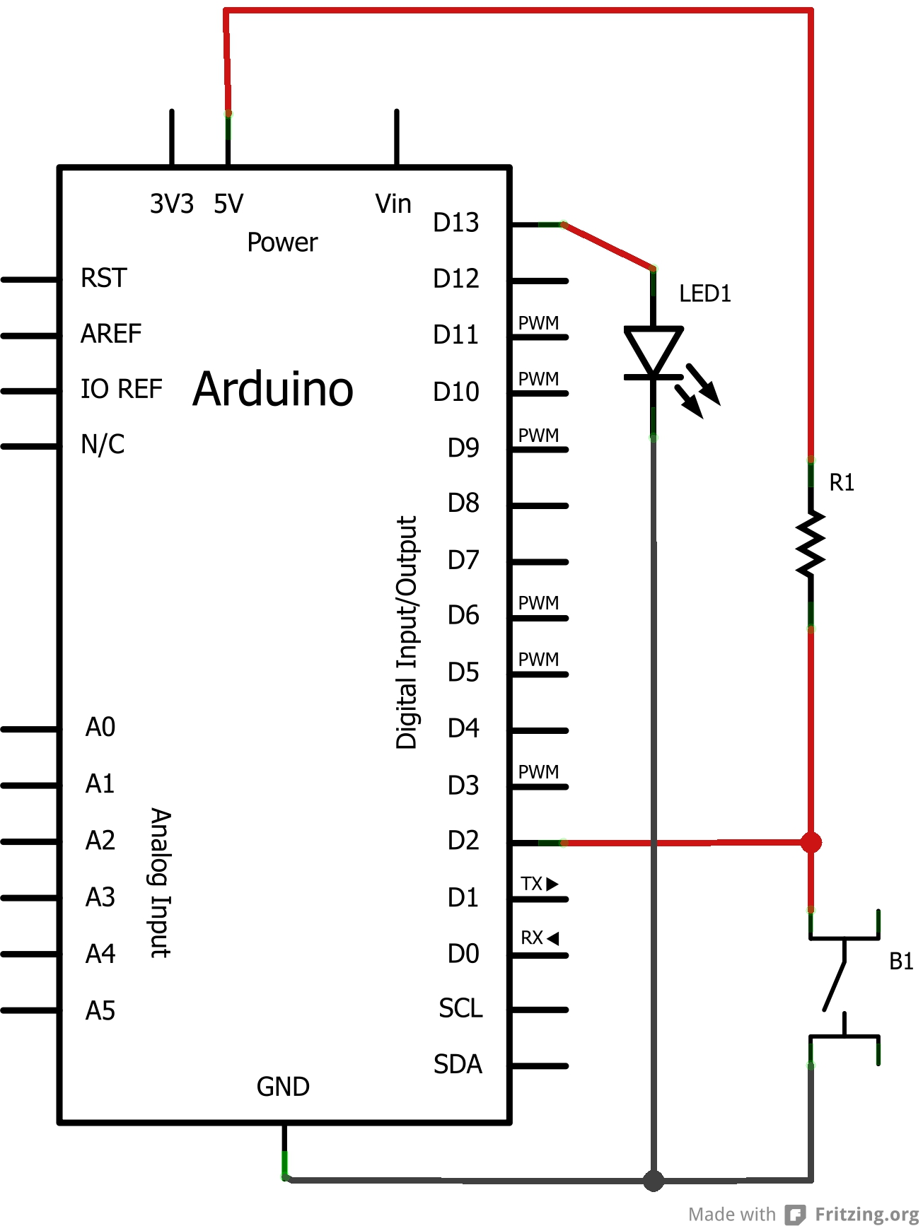
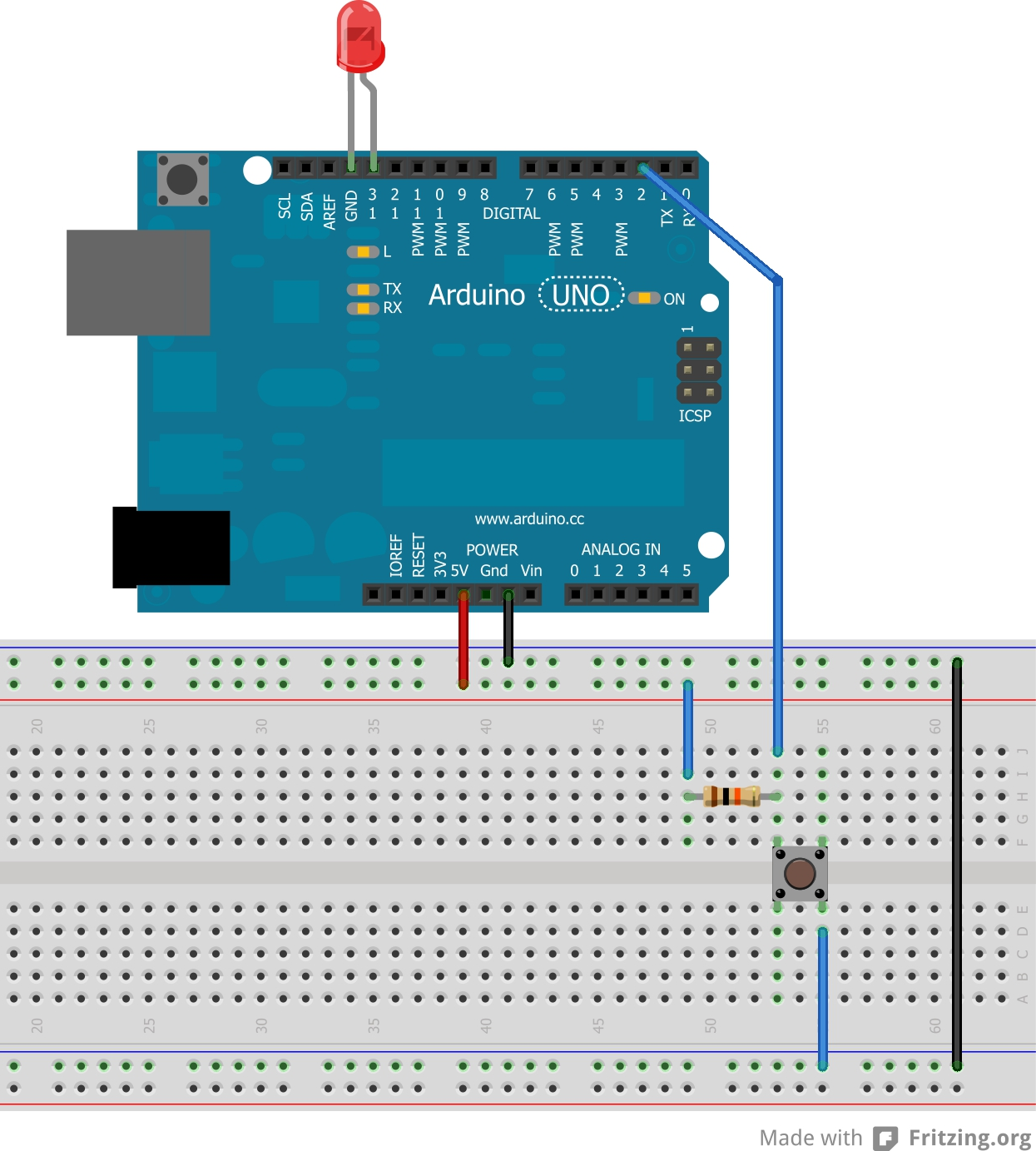
In addition to the button, you also need a pull-up resistor. “Pull-up” describes,not the type of resistor, but the role it plays in this circuit. See the sidebar “Pull-Up Resistors” for more on that. Figure 6 is the schematic, including the button and its pull-up resistor, plus the LED from the first part of this project. Figure 7 shows how to lay the components out on the breadboard.
Edit the Code
Let's add to the blinky LED sketch. Add another precompiler directive, to define “button” as an alias for pin 2. Also declare an integer variable named buttonState, to store the state of the button when you read it in, and initialize the variable with a value of 0.
In the setup() function, add a call to pinMode() that sets the button pin to be an input. In the loop() function, read from the button and assign the result to the buttonState variable.
buttonState = digitalRead(button);
Next, write an if/else statement that lights the LED depending on the state of the button. Because you are using a pull-up resistor instead of a pull-down resistor, pin 2 will report that it is HIGH when the button is not pressed, and LOW when it is pressed. Therefore, your if statement will be backward from what you might have expected.
if (buttonState == 1)
{
  digitalWrite(led, LOW);
}
else
{
  digitalWrite(led, HIGH);
}
No, I don't like if/else statements, either, so let's refactor that to a single line.
digitalWrite(led, 1 - buttonState);
It is 1 minus buttonState in order to invert the value, which is needed because of the pull-up resistor. 1 - 0 = 1, and 1 - 1 = 0, so that statement writes a LOW voltage to the LED when the button's pin is HIGH, and vice versa.
See Listing 1 for the final sketch.
Listing 1: Light an LED when a button is pressed
#define led 13
#define button 2
int buttonState = 0;

void setup()
{
  pinMode(led, OUTPUT);
  pinMode(button, INPUT);
}

void loop()
{
  buttonState = digitalRead(button);
  digitalWrite(led, 1 - buttonState);
}
Upload the Sketch
When you first connect the USB cable, you will see the LED blinking as the Arduino runs the prior sketch. When you upload this one, you will overwrite the old sketch.
Expected Results
Here are the steps you just completed.
- You used a breadboard to add additional components to your circuit.
- You read a schematic to understand what to build.
- You used a pull-up resistor to make your digital pin read predictable, reliable results.
- You edited your sketch to read from an input, evaluate conditional logic, and respond by controlling an output.
The LED should remain off by default. When you press and hold the button, the LED will light for as long as you are holding the button.
Continue to Play
Now that you have completed “hello, world,” what else will you build with this small computer that manifests your code in the real world?
Add a Motor
The Arduino IDE ships with a number of libraries that make it straightforward to interact with more complex components, such as a servo motor. Beyond that, a vibrant open-source community contributes hundreds of libraries.
Unlike a motor that spins continuously, a servo motor can be set to a specific position, usually between 0 degrees and 180 degrees. The Arduino's Servo library lets you declare a Servo object and tell it to “write” to a specific location.
This sketch uses the Servo library and instructs a servo motor to wave its arms back and forth.
#include <Servo.h>
Servo robot;

void setup()
{
  robot.attach(9);
}

void loop()
{
  robot.write(105);
  delay(500);
  robot.write(75);
  delay(500);
}
The #include <Servo.h> statement brings the library into your sketch. The Servo robot; line declares a variable named robot of type Servo. In the setup() function, the robot is initialized to write to pin 9. In the loop() function, the Servo class's write() method takes a value between 0 and 180, causing the Arduino to send the corresponding voltages to the servo motor so that it moves to the right position.
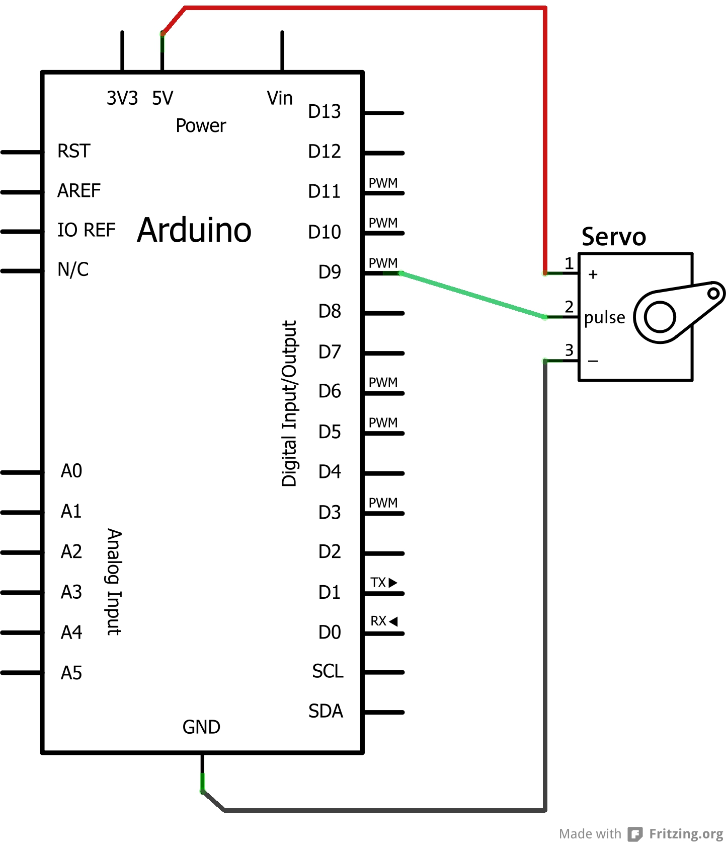
Connecting the servo motor is also straightforward. A servo has three wires: one goes to power, one to ground, and one to the Arduino pin that will give it instructions. Figure 8 shows the schematic. The datasheet for the servo will tell you which wire is which.
More Outputs and Inputs
You've seen two outputs, an LED and a motor, and one input, a pushbutton. And there are so many more. From LCDs, speakers and MIDI, motors and relays, to GPS, bar code readers, magnetic field sensors, and touch sensors, your Arduino can sense the world around it and execute your code to change its environment.
The Arduino Playground, a community-edited wiki, presents an imagination-spurring list of outputs and inputs at https://playground.arduino.cc/Main/InterfacingWithHardware/.
Good Habits
On your journey, two strategies will accelerate your progress, and they both relate to hanging on to what you've learned.
First, keep a notebook. When you figure something out or learn a new concept, write yourself a note about it. Keep your drawings and schematics as you design and plan projects. It's surprising how quickly and thoroughly you can forget something when you don't work with it every day. Give yourself a reference so that when you sit back down to a work in progress, you can remind yourself where you left off.
Second, use source control and commit often. (I open-source my sketches on GitHub.) Work a project incrementally, getting a small part working before going onto the next, and check that code into source control with a descriptive comment at each small step. Similar to your notebook, your commit history serves as an annotated reference as you learn.
What's Next?
With outputs and inputs, you have the building blocks you need to make fun, interactive projects. What will you do next? Are there sensors and alerts that might be handy to have around the house? Electronics could play a role in your art. Consider adding some brains to your next Halloween costume. What projects might the kids in your life like to build with you?
Build things. Share them. Have fun.