


The Basics of GDI+
In graphical user interfaces such as Microsoft Windows, drawing on the screen is an important task.
Everything displayed on the screen is based on simple drawing operations. Often, environments such as Visual Basic abstract those drawing operations away from the developer. However, the same drawing operations still take place under the hood. In Visual Studio .NET, developers have easy access to that drawing functionality whenever they need it through a technology called GDI+. Using GDI+, developers can easily perform drawing operations such as generating graphs or building custom controls.
Whenever you create a Windows Forms (WinForms) application .NET uses(and includes) GDI+ by default. The System.Drawing namespace contains all GDI+ functionality (as well as a few sub-namespaces). GDI+ provides all the basic drawing features, such as drawing lines, curves, circles, ellipses, strings, bitmaps, and more. GDI+ also gives developers the ability to fill areas with colors, patterns, and textures. This article will explain some of the basic drawing mechanisms that GDI+ provides.
The Graphics Object
All GDI+ drawing is done using a Graphics object. This object has a large number of methods that encapsulate drawing operations on a drawing “canvas.” GDI+ supports a number of drawing canvases including: windows, bitmaps, and printer pages. Depending on the type of drawing canvas, the Graphics object is created or retrieved in a number of different ways. If you want to modify the contents of a bitmap file you would create a Bitmap canvas using the FromImage() method. This article will focus on one type of canvas: the window.
Drawing in a WinForms-form is a somewhat peculiar task, because it is not enough to draw the graphic once. Instead, the “drawing” may have to be “refreshed” (re-drawn) whenever a window requires repainting. Repainting can happen whenever a user resizes a window or one window overlaps another window and then something brings the overlapped windows to the front.
So how do you know when to start drawing? The easiest way is to listen to the Paint event that is fired by every window (or control for that matter). The Paint event is a very good choice for drawing-logic because it fires whenever you need to refresh the display, and because part of the Paint event arguments (parameters) is a handle to the Graphics object. You can access the Graphics object via the following C# code:
private void Form1_Paint(object sender,
System.Windows.Forms.PaintEventArgs e)
{
Graphics g = e.Graphics;
}
Visual Basic .NET supports the same construct:
Private Sub Form1_Paint( _  ByVal sender As Object, _  ByVal e As _  System.Windows.Forms.PaintEventArgs)  Handles MyBase.Paint
Dim g As Graphics = e.Graphics
End Sub
Once you have a Graphics object, you are ready to draw on the window.
Note that whenever I refer to a “window” as the drawing canvas, I also mean “control.” Internally, controls are handled just like windows.
Simple Line Drawings
A fundamental task performed by the graphics-object, is drawing lines and curves. You can use a number of methods for this purpose.
In GDI+, unlike in regular (older) GDI, drawing lines and filling areas are two entirely different operations.
When you draw lines, you must consider a number of fundamental things. For example, you need to choose what kind of line to draw.. Do you want a straight line, or a curve? Do you want a simple, single line, or do you want to draw a complex line composed out of many segments? Maybe you want to draw a closed shape that forms a completely enclosed area with an identical start and end point (such as a circle, rectangle, or polygon)? Depending on the desired shape of the line, different methods are available to generate them.
Less obvious than the position and shape of the line, are the parameters for a line. You might ask, “What parameters can I specify for a line?” You can specify the following parameters: attributes such as color and thickness, start and end-points, and the shape of the end of a line such as whether the line ends in a rounded or square “head” or ends in an arrow.
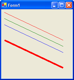
In GDI+, lines are represented by Pen objects. Pens encapsulate all the attributes described above. GDI+ provides a number of default Pen objects, such as pens of different colors. The following code demonstrated drawing a simple straight line using different pens. (This is VB .NET code. C# developers add a semi-colon at the end of the line):
g.DrawLine(Pens.Red,10,10,200,100)
g.DrawLine(Pens.Green,10,30,200, 120)
g.DrawLine(Pens.Blue,10,50,200,140)
If you want to adjust the thickness of the used pen, you need to instantiate a custom pen object. This example generates a 5-pixel thick red pen and uses it to draw another line:
g.DrawLine( _ New Pen(Color.Red, 5), _ 10, 100, 200, 190)
You instantiate the Pen using the line color and thickness as parameters. Once again, the C# version of the code is very similar: Simply add a semi-colon at the end and write the “new” keyword in lower case.
Figure 1 shows the result of all 4 lines of code listed above.
If you play with the DrawLine() method a bit, you will discover that it has a large number of overloads, though the result of these overloads is the same. You can just take different paths to your destination. I encourage you to experiment with the different options.
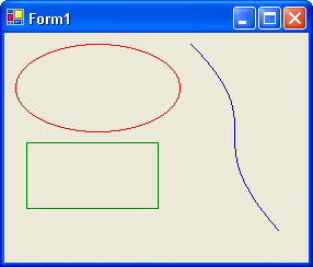
For instance, you can draw circles and ellipses:
g.DrawEllipse(Pens.Red, _ 10, 10, 150, 80)
Similarly, you can draw rectangles with this code:
g.DrawRectangle(Pens.Green, _ 20, 100, 120, 60)
The following example draws a Bezier curve. Explaining the details of Bezier curves is beyond the scope of this article (Time to drag out your old math text books…):
g.DrawBezier(Pens.Blue, _ 170, 10, 250, 90, 170, 90, 250, 180)
Figure 2 shows the result of these 3 drawing operations.
Drawing Complex Figures
Drawing lines and rectangles works very well when you need to create custom Windows Forms controls. If you want to create more complex and artistic drawings such as diagrams, GDI+ lets you draw more complex shapes. In GDI+, this is accomplished using graphics paths.
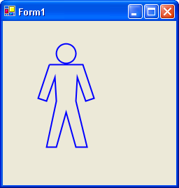
GraphicsPath objects encapsulate a number of line segments. You add individual segments via drawing primitives, such as AddElipse() and AddLine(). GraphicsPath objects make it relatively simple to generate complex shapes by automatically connecting line segments. Consider the following code for instance:
Dim Person As New GraphicsPath()
Person.AddEllipse(23, 1, 14, 14)
Person.AddLine(18, 16, 42, 16)
Person.AddLine(50, 40, 44, 42)
Person.AddLine(38, 25, 37, 42)
Person.AddLine(45, 75, 37, 75)
Person.AddLine(30, 50, 23, 75)
Person.AddLine(16, 75, 23, 42)
Person.AddLine(22, 25, 16, 42)
Person.AddLine(10, 40, 18, 16)
g.DrawPath(Pens.Blue, Person)
This simple example generates the shape of a human (well… as close as I can get with my limited artistic abilities) and renders it on the screen as shown in Figure 3.
Note: The GraphicsPath class is a member of System.Drawing.Drawing2D. Make sure to import that namespace or reference the class by its fully qualified name.
Graphics Quality
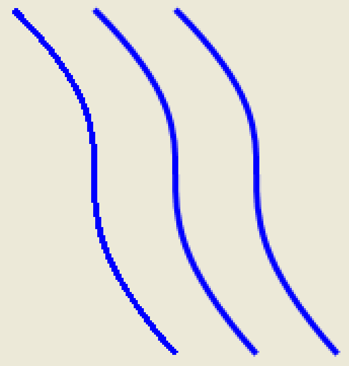
At this point it is important to discuss the quality of the graphics you render. When you draw vertical and horizontal lines, quality is not a big concern because GDI+ draws lines simply by setting the colors of pixels that are all lined up in a row. When you draw lines at an angle (or curves), things get a bit more tricky. The pixels on your monitor do not correlate with the pixels that should be set based on the mathematical calculation of the drawn line. So the rendering system needs to decide what pixels to use and which ones to leave out. This process is known as aliasing.
Aliasing leads to poor looking drawings?you can clearly see a “step” or “jagged” effect. One solution to this problem is a technique known as anti-aliasing. Using this technique, the rendering engine uses different color variations for pixels that should only be partially included, leading to a much smoother appearance to the human eye.
You can tell GDI+ how you would like it to optimize a drawing. Consider the following code for instance:
Dim oPen As New Pen(Color.Blue, 3)
g.SmoothingMode = _  SmoothingMode.HighSpeed
g.DrawBezier(oPen, _  10, 10, 90, 90, 10, 90, 90, 180)
g.SmoothingMode = _  SmoothingMode.AntiAlias
g.DrawBezier(oPen, _  50, 10, 130, 90, 50, 90, 130, 180)
g.SmoothingMode = _  SmoothingMode.HighQuality
g.DrawBezier(oPen, _  90, 10, 170, 90, 90, 90, 170, 180)
This renders three similar Bezier Splines at different quality settings. Figure 4 shows a magnified version of the result. Naturally, you want the high-quality version, but quality comes with a cost: performance. Which method you choose will depend on the performance requirements for your application.
Filling Shapes
As mentioned before, GDI+ also offers ways to fill shapes. The techniques you use to fill shapes is very similar to drawing shapes, except for fill operations you use Brushes. A GDI+ Brush is similar to a GDI+ Pen, but Brushes are often much more powerful.
The following example shows how to draw an ellipse filled with a green brush:
g.FillEllipse(Brushes.Green, _ 10, 10, 150, 80)
In a slightly more complex operation you can fill a shape with a pattern using something called a Hatch Brush. In this example, you can create a diagonal brick effect:
Dim oBrush As New HatchBrush( _  HatchStyle.DiagonalBrick, _  Color.Blue, Color.Firebrick)
g.FillEllipse(oBrush, _  10, 100, 150, 80)
You can also choose to use a bitmap as a Brush. In this code snippet you see that I load one of the default images that ships with Windows into a Bitmap object, then create a TextureBrush based on that image, and use it to fill the ellipse:
Dim oBmp As New _   Bitmap("C:\WINDOWS\GREENSTONE.BMP")
Dim oBrush2 As New TextureBrush(oBmp)
g.FillEllipse(oBrush2, _   200, 10, 150, 80)
Furthermore, you can create gradient brushes as in the following example:
Dim oRect As New _   Rectangle(200, 100, 150, 80)
Dim oBrush3 As New _   LinearGradientBrush(oRect, _
Color.Red, Color.Blue, _   LinearGradientMode.Vertical)
g.FillEllipse(oBrush3, _   200, 100, 150, 80)
I used a Rectangle object to first specify an area that I wanted to confine the gradient to. I then defined two colors, as well as an angle (“Vertical” in this case, but you could also use a numeric value).
Note: The LinearGradientBrush class is a member of System.Drawing.Drawing2D.
Figure 5 shows a combined result for the last 4 examples.
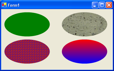
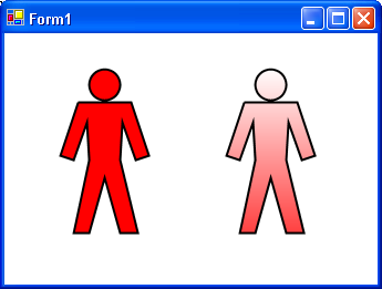
I personally favor gradient brushes. I think shapes filled with a gradient look more professional than shapes filled with a single color. Consider Figure 6, which shows the human shape filled with two different brushes (solid and gradient). Here's the code that fills the “person” path I created before:
Dim oRect As New _   Rectangle(0, 0, 100, 100)
Dim oBrush As New _   LinearGradientBrush(oRect, _
Color.White, Color.Red, _   LinearGradientMode.Vertical)
g.FillPath(oBrush, Person)
Whenever you want to create a shape with a fill color as well as an outline (a technique sometimes also referred to as “cell shading”), you need to perform both actions separately (unlike in conventional GDI). Perform the fill operation first and render the outline second to make sure potential drawing inaccuracies do not “cut” through the outline.
The Coordinate System
Whenever you use GDI+ to draw, you use the GDI+ coordinate system. By default, the coordinate system maps directly to the pixels on your monitor. However, you may want a different behavior. You can, in fact, transform the coordinate system if you have special needs. Consider the person shape you created above. The position of that shape is defined by the graphics path object you use. But what if you wanted to draw multiple copies of that shape multiple times in multiple locations?
The easiest way to do so is to alter the virtual coordinate system. The Graphics object offers a number of methods to do so. Here's an example:
g.DrawPath(Pens.Black, Person)
g.TranslateTransform(75, 0)
g.DrawPath(Pens.Black, Person)
g.ResetTransform()
This draws the first person shape at the default position, then moves the origin (point 0,0) of the coordinate system 75 pixels to the right, and draws the shape again. Without the ability to move the coordinate system around, you'd have to create another person path identical to the first one, but located at a different position.
You need to reset the transformation after GGDI+ completes the drawing operation in your virtual coordinate system. Otherwise, GDI+ will offset your future drawings to the right.
Zooming
You may notice that the person shape in my figures seems to be a bit bigger than the one you get when you run the samples. That's because I made GDI+ zoom the shape before I took the screen shot. I used the following scale transformation to do the zooming trick:
g.ScaleTransform(2, 2)
g.DrawPath(Pens.Black, Person)
g.ResetTransform()
This zooms everything by a factor of 2 on both axes. You could zoom at different factors for each axis. For instance, you could leave the height of the person at the original level, but change the horizontal zoom:
g.ScaleTransform(2, 1)
Of course, this makes the little guy look terribly overweight. Most of the time you should zoom at equal factors for both axes.
Rotating
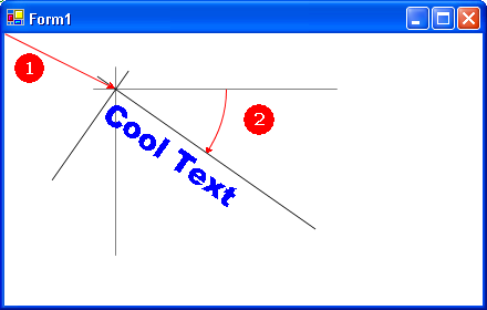
Another interesting transformation of the coordinate system is its ability to rotate. This allows for fancy tricks such as rendering text at an angle:
g.TranslateTransform(100, 50)
g.RotateTransform(35)
g.DrawString("Cool Text", _  New Font("Arial Black", 20), _  Brushes.Blue, 0, 0)
g.ResetTransform()
This example moves the origin to a new point and then performs a subsequent rotation. Drawing the text then becomes trivial, as you render it at (virtual) position 0,0. Figure 7 shows the result as well as an illustration of the performed transformations.
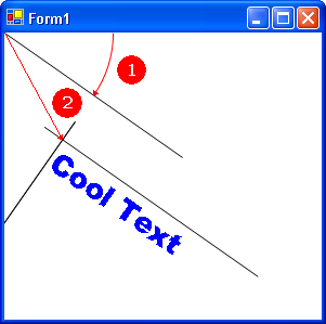
Note that the order in which you perform transformations is of crucial importance. Figure 8 shows what happens if you change the order of transformations As you can see, the resulting position of the text string is different. because I moved the coordinate system. Transformations can be very tricky to do correctly. I generally recommend that you perform rotations after all coordinate movement.