


Class diagrams are among the centerpieces of the Unified Modeling Language.
They are critical for helping you design classes that will serve as building blocks for your application. This article will cover the basics of class diagrams and help you see how you can use them in your software development?especially in building your business object classes.
In this second article in the series, we take a close look at UML class diagrams. Class diagrams are most often used in the elaboration and construction phase of software projects. When used in conjunction with UML sequence diagrams (covered in the next article in this series), they can help you produce well-designed families of classes that form the foundation of flexible and extensible software applications.
This article provides a practical overview of the most commonly used features of class diagrams. It is not intended to be a completely comprehensive guide to class diagrams?that would require a book; and, in fact, it's highly recommended that you refer to The Unified Modeling Language User Guide by Booch, Rumbaugh and Jacobson (Addison-Wesley) for the complete details on class diagrams. For the most up-to-date information, check out the latest official version of the UML specification at www.omg.org/technology/uml/index.htm.
Why Use Class Diagrams?
If you're creating monolithic applications where the application and data access logic is melded together inside the user interface, you will find little use for class diagrams?or the entire UML for that matter! Fortunately, many software developers are beginning to understand the importance of creating component-based applications that can be easily maintained, extended and scaled from the desktop to the Internet. This requires that you create families of classes (most importantly business object classes) that have crisp boundaries and a balanced distribution of responsibilities. Class diagrams can help immensely in this regard. They enable you to design your classes, which become the building blocks of your application.
Class diagrams allow you to document the structure (attributes and operations) of classes. They are also extremely useful for understanding relationships between classes, inheritance hierarchies, and responsibilities of the entities that provide the system behavior.
Modeling Class Structures
As shown in Figure 1, classes are graphically represented as a rectangle containing three compartments. The upper compartment contains the name of the class, the middle compartment contains a list of attributes and the bottom compartment contains a list of operations.
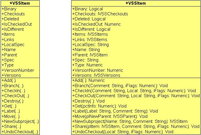
You can display classes with as little or as much detail as desired. Figure 1 shows two different representations of Microsoft Visual SourceSafe's VSSItem class. The class on the left side shows a simpler representation of the class with just the attribute and operation names displayed. The class on the right side shows additional detail?the type and value of properties and the parameters (their types) and return values of operations.
To the left of each attribute and operation is a symbol that indicates the item's visibility?public, protected, private or implementation (see the Visibility sidebar for details). When showing full detail, attribute names are followed by a colon and the type and default value of the attribute.
Operation names are followed by parentheses. When showing full detail, the parentheses hold the argument name followed by a colon and the type and default value of the argument. A colon and the type of the operation's return value follow the parentheses.
Modeling Class Relationships
There are four different relationships that can be modeled in class diagrams?generalization, dependency, association and realization.

Generalization
The most common class relationship is generalization (inheritance), which links generalized classes to their specialized subclasses (Figure 2). Generalization is shown as a line with a solid arrowhead pointing from the specialized child class to the generalized parent class.
During analysis and design, you may come across classes that have similar attributes and operations. Rather than duplicating these in distinct, unrelated classes, you can move these common elements up to a generalized class from which the specialized ones inherit. Generalization specifies an “is-a” relationship between classes.
Abstract, Concrete, Root and Leaf Classes
One opportunity for using generalization that is often overlooked is creating abstract classes that define the interface for a family of related classes. When you have a situation where there are multiple possible behaviors for a given class, rather than using CASE statements to dictate the alternate actions, you can break the single class into a family of classes?one class for each different type of behavior. To ensure that all classes in the family have the same attributes and operations, you create an abstract parent class from which all specialized classes inherit.
For example, Figure 2 shows a family of data access classes. In the real world there are a variety of ways that you can access data?ADO, XML, various types of cursors (particularly in Visual FoxPro). Rather than creating a single data access class that contains all of the different types of data access behavior, you can create one class for each different type of behavior. In Figure 2, CDataAccessBase is an abstract class that represents the generalized, or abstract concept of data access. In the UML, showing the class name in italics indicates that the class is abstract. Typically, there is little or no code in an abstract class.
The only reason the CDataAccessBase class exists is to define a standard interface (attributes and operations) that are inherited by the family of data access classes. Its operations such as New(), Delete(), Save() and Requery() represent the different actions you can perform on data. These operations are also abstract. They represent the things you can do with data, but they contain no actual code to perform these actions. In the UML, abstract operations are also shown in italics. The actual implementation code is stored in the specialized subclasses. These subclasses are known as concrete classes because they contain the solid, real-world implementation code that knows how to operate on a particular type of data.
In the UML, you can also specify that a class may have no children. This is known as a leaf class and can be specified by showing the property “leaf” under the class name. You can also specify that a class may have no parents. This is known as a root class and is specified by writing the property “root” below the class name.
Dependency
At times, classes depend on the existence of other classes for a variety of reasons. In class diagrams, dependency usually indicates that the operations of a client class call operations of the supplier class. In the UML, a dependency is rendered as a dashed line, often with an arrowhead showing the client-to-supplier direction, and possibly a label describing the dependency relationship (see the sidebar for a description of additional types of dependencies).
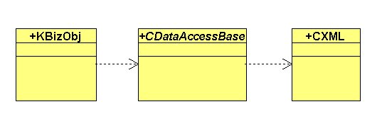
Figure 3 shows a dependency relationship between a business object class (KBizObj), a data access class (CDataAccessBase) and an XML manipulation class (CXML). The business object class depends on the existence of the data access class for accessing and manipulating data. In turn, the data access class depends on the existence of the XML class for generation and manipulation of XML strings.
Association
An association specifies a structural relationship and pathway for communication between classes. An association is graphically represented as a solid line connecting different (or in some cases, the same) classes. The end of an association where it connects to the class is known as an association end.
By default, navigation across an association is assumed to be bi-directional. If you want to model one-way navigation, you can add an arrow indicating the direction of navigation.
The most common properties of associations are: name, role, multiplicity, aggregation, composition and visibility.
Name
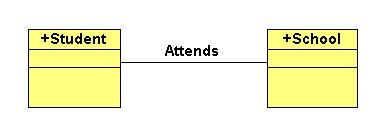
You can optionally give an association a name to indicate the nature of the relationship. The name is usually a verb or verb phrase. For example, as shown in Figure 4, a Student “attends” a School. If you specify role names (described below), you typically don't need to specify a name for the association.
Role
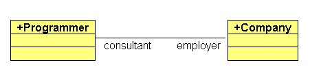
When a class participates in an association, it plays a specific role in that association. A role can optionally be specified at each end of the association. For example, in the association shown in Figure 5, a Programmer plays the role of a Consultant in association with a Company that plays the role of an Employer.
Multiplicity
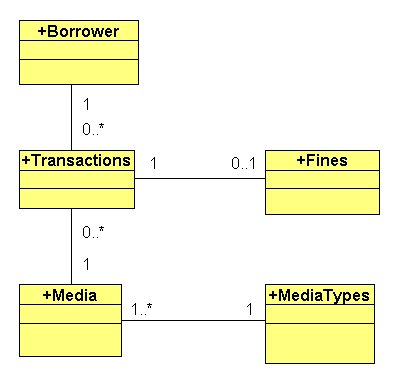
Multiplicity specifies the number of classes that can be connected across an association. When determining multiplicity for an end of an association, ask yourself the question “How many instances of a class at this end may be associated with a single instance of the class at the other end”?
Figure 6 demonstrates multiplicity in class associations found in a software application designed for Libraries. A Borrower can have one or more Transactions (checking in or checking out media) and a single Transaction belongs to only one Borrower. A Transaction can have zero to one fines and a particular Fine is associated with a single Transaction. A given piece of Media has only one Media Type and a single Media Type may be assigned to one or more Media.
The following table specifies the possible multiplicity values for relationships. As shown in the Description column, literals stand for any number.
Aggregation
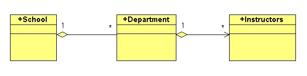
Normally, when you create an association, the classes on either end of the association are peers. However, if you would like to indicate a whole/part relationship where one class represents a large whole consisting of smaller parts, you can use an aggregation association. Graphically, an aggregation looks just like an association with the addition of an open diamond at the “whole” end.
Figure 7 illustrates an aggregation relationship between a School (whole) and Department (parts). In turn, a Department (whole) is associated with Instructors (parts).
Composition
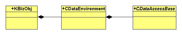
Composition is a special type of aggregation that indicates strong ownership and coinciding lifetime between the whole and parts. It specifies that an object may only be part of one composite at a time. It also means that the composite manages the creation and destruction of its parts.
As shown in Figure 8, the graphical representation of composition is similar to aggregation, but with the diamond filled in. It illustrates a composition relationship between a business object, its data environment and the data environment's data access classes.
Visibility
For each relationship, you can specify the type of access allowed for the relationship: public, private or protected. These have the same meaning as the visibility attribute applied to attributes and operations.
Realization
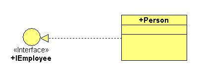
Realization is a cross between a dependency and generalization relationship. In realization, one class specifies a contract that another class guarantees to carry out. This is most often used between classes and interfaces.
An interface is a named set of externallyvisible operations that specify the behavior of a class and contains no implementation code of its own. One example of this is Microsoft's COM (Component Object Model) interfaces. In a realization relationship between a class and an interface, a class realizes, or implements the operations specified by the interface.
As shown in Figure 9, the graphical representation of the realization relationship is usually shown as a dashed line with an open arrowhead. In this example, the Person class realizes the IEmployee interface.
Summary
The UML class diagram is extremely useful for defining classes, which are the primary building blocks of your application. Taking the time to analyze the problem domain and design classes properly is well worth the effort. Logically partitioning your application logic among well-designed classes will help you create a strong foundation on which to build highly maintainable, flexible and extensible applications.
| Value | Description |
|---|---|
| 0..0 | Zero |
| 0..1 | Zero or one |
| 0..* | Zero or more |
| 1..1 | One |
| 1..* | One or more |
| * | Unlimited number |
| Exact number (Example: 4) | |
| Exact number or more (Example: 4..* indicating 4 or more) | |
| Specified range (Example: 4..13) | |
| Specified range or exact number (Example: 4..13,31 indicating 4 through 13 and 31) | |
| Multiple specified ranges (Example: 4..13, 31-41) |