


When creating a Windows DNA application, it is not enough to start creating COM objects and run them under MTS.
Rather what is needed is a standard approach to analyzing DNA applications. This article provides a pattern language for COM objects. The purpose of this pattern language is to standardize discussion of types of components so that the design of these applications becomes more standardized.
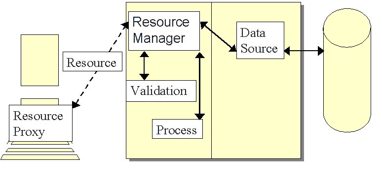
Let's begin by looking at a Windows DNA application. A DNA application consists of three logical tiers: a user interface tier, which presents information to the user and standardizes the user's movements through the system, a middle or business tier, which provides validation, business rule processing and standardization of the data, and the data tier, which is the storage location for persisting information. (See Figure 1.)
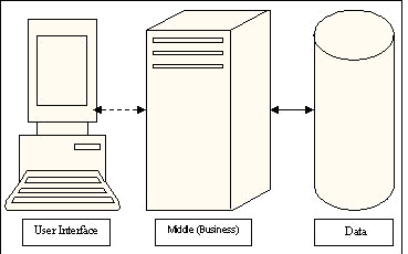
The middle and data tiers can be placed on multiple servers for scalability and security reasons, leading to a theoretically unlimited number of physical servers for any given system. It is for this reason that DNA applications are sometimes known as n-tier systems. We will be dealing with the logical design of a DNA application, and will delve deeper into each of the three tiers as we progress further with our DNA development.
Note that we've shown the connection between the User Interface tier and the Middle tier with a dotted line. This communication is done in a loosely connected fashion. In other words, unlike the communication between the middle tier and the data tier where we can assume a permanent connection between the two servers, the front end may be a web page that connects and disconnects on every request. We need to take that into account when building our DNA application. In fact, it will be easier to just assume that no permanent connection exists when designing our applications, since that will work even in cases where we have a connection.
The Middle Tier: A Structural Overview
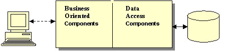
Let's take a closer look at the business tier. It is the most complex of the three tiers because it alone communicates with both of the other tiers. In order to simplify this tier, we recommend thinking of the components in this tier as belonging to one of two groups: the group that talks to the user interface, implementing the rules; and the group that talks to the database. Each group should be replaceable. For instance, if you change from a SQL Server to an Oracle back end, you should not have to modify any of the rules. Likewise, if a rule changes, you shouldn't have to modify any of the data access logic. Additionally, you may find that multiple rules use the same view of the data; so separating out the components that provide views of the data from the manipulation of that data makes sense.
Standard Stereotypes for the Middle Tier
There are five stereotypes used in developing a Windows DNA application. This table lists them, describes them and provides the default value that is commonly used for setting up MTS transactioning:
Let's take a look at a simple example of how a DNA application might work. The following table uses these objects:
- rmClient - A client resource manager
- dsClient - A client data source
- rsClient - A client resource
- vldClient - A client validation object
As you can see, the UI developer only needs to know about the public interface of the resource managers. The resource manager acts as a façade into validation objects, process objects and data sources. The data sources are the only objects that need to know about the structure of the database and any calling conventions for that database.
DNA Stereotypes: A Diagram
Viewing our stereotypes in the context of the divided middle tier gives us this picture:
Figure 3 doesn't give a complete picture, since resources are actually used to pass information between all of the components (for instance when the Resource Manager calls a Validation Object), but it was left out to make the picture clearer.
Save: A Sample
Let's take a look at how these stereotypes help in creating an MTS-aware application. To do that, we'll look at how we would handle saving information; one of the more typical, yet complex functions that brings into play transactions as well as the possibility of role-based security.
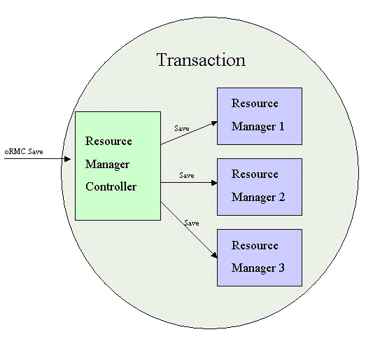
When a particular function such as Save occurs under MTS, it often requires that the save process actually saves multiple resources. For instance, saving a new invoice may involve changes to customer, invoice, invoice details and inventory resources. In order to accomplish this cross component transactioning in MTS we must have one component marked as Requires New Transaction and subservient transactions that are marked as either Supports Transactions or Requires Transactions. These subservient components enroll in the main transaction.
In order to accomplish this, we use an object that is of the Process stereotype. Let's call it a Resource Manager Controller (RMC). The RMC is the component that manages the main transaction. When a save is issued by the user interface, it actually packages all of the necessary resources and sends them to the RMC. Thisbegins a transaction, then delegates the actual processing of that transaction to the various resource managers.
When packaging the necessary resources for the RMC, we have to worry about a number of things including getting all the data to the middle tier, and managing any relations between the resources so that they are saved in the proper order. This means that a developer has to be able to define any number of parent child relationships in a variety of different configurations. In this manner, data sources and resource managers can be defined once, with the relationships between resources defined at run-time by an application. This means that once a set of middle-tier components has been created for a company, adding a new front-end simply consists of defining the relations between those components and providing an appropriate UI.
In order to accomplish this, we have the front end use XML to define the parent-child relations between the various resources, and the RMC uses that information to delegate the calls to the resource managers in the proper order. In other words, the call to an RMC will typically consist of a passed XML string, followed by the passing of each resource that has been modified on the front end. At that point, the RMC's Save() method would be called.
In order to make life easier for the front-end developer, having a variety of proxy objects for the RMC and the Resource Managers is helpful. The Resource Manager Proxy Controller (RMPC) manages the Resource Manager Proxies on the form. Each of these proxies handles calling to their namesakes on the middle tier, and also set up the calls appropriately. For instance, the RMPC can be tasked with creating the XML that specifies which resources need to be saved and the order in which the save should occur.
When the RMC's Save() is called, the RMC begins the MTS transaction by creating the MTS Context Object. It then tells the primary resource to validate itself. The primary resource passes the validation off to its validator, and then calls the validation of each of its children in turn. If the primary resource (and all of its children) pass the validation test then the Save() method executes, again calling each one in turn. Once the Save() method executes, the result is passed to the method where the transaction is either aborted or committed. A Sequence diagram of the Save is listed below.
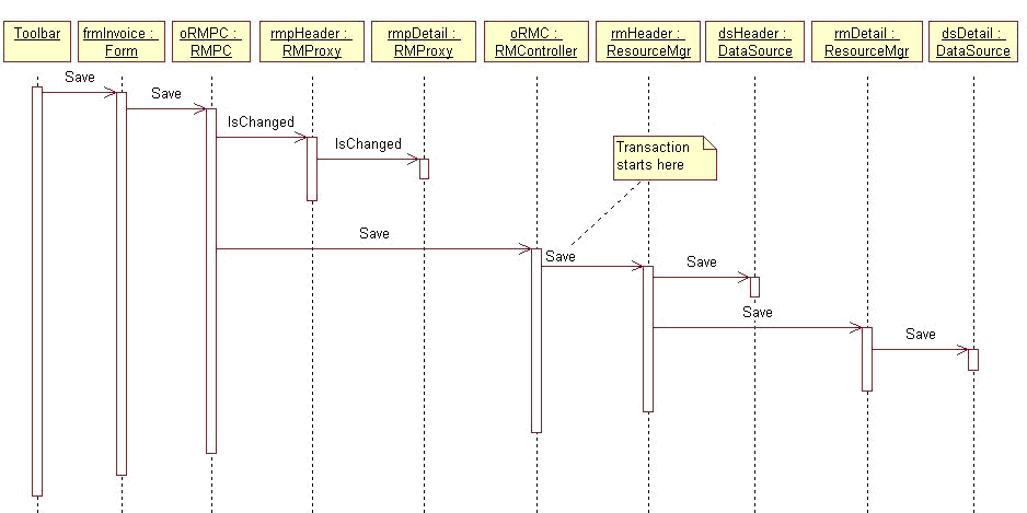
In this diagram, the user clicks on a toolbar's “Save” button. It tells the current form to save which calls a proxy object for the RMC. This object checks with each resource manager proxy to see if any data has changed. If nothing has changed, no call to the middle tier will be made. If data has changed, it will be packaged and sent to the Resource Manager Controller. That is where the transaction will begin, and all resource managers will handle the saves through their data sources.
Conclusion
The physical separation of the data by the individual tiers, the requirement to use MTS Transactions when updating data, and the requirement that developers be able to create complex parent child relationships in the interface, presented some interesting challenges. By thinking about the types of objects that we need to use, we can begin to remove some of the complexity by providing standardized behaviors for our objects and rules of thumb for transaction management.
The use of a process stereotype as a controller object on the business tier allows the developer to automatically handle complex save requirements by having a proxy recreate the UI environment in the business layer, where it is wrapped in an MTS transaction, validated and finally saved.
By using these stereotypes to design and create our DNA application, our discussions become clearer and provide for a simpler set of services to the front-end application developer.
Table 1: Sterotypes used in Windows DNA applications.
| Stereotype | Description | MTS Transactioning Default |
|---|---|---|
| Resources | Resources are the "containers of state" for our components. They are passed from tier to tier and component to component where they are modified when necessary. They will often take the form of ADO RecordSets or XML data streams. | Not hosted by MTS |
| Resource Managers | Resource Managers are the UI tier's view into the business tier. They are business aware sets of components that provide the public interface used by the front-end developer. | Supports Transactions |
| Data Sources | Data Sources are components that handle creating, loading and updating Data Sets as necessary. | Requires Transaction |
| Validation Objects | Validation Objects contain the validation for a Data Set. | Supports Transactions |
| Process Objects | Process Objects perform any validation and processing that has to occur across multiple Data Sets. | Requires New Transaction |
Table 2: Some `example` objects that could be found in a DNA applicaton.
| Tier | Object | Method Call | Returns |
|---|---|---|---|
| UI | RmClient | GetClientByID(1) | |
| rmClient | DsClient | GetClientByID(1) | rsClient with data for Client #1 which is returned to rmClient and then to the UI |
| UI | Modifies the data in rsClient | ||
| UI | RmClient | Save(rsClient) | |
| rmClient | VldClient | Validate(rsClient) | rsClient with any changes required by the validation and a validation success message |
| rmClient | DsClient | Save(rsClient) | Success message is passed back after the rsClient changes are updated to the server. |